


Are you a Trade Professional?
Become a smart heating expert.

Why become an IRSAP NOW installer?

Install our innovative, intuitive products for a home with smart heating.

Stand out by becoming an IRSAP NOW installer.

In case of problems during installation, you can consult our FAQs or contact our chat.

Offer safety to your customers with the 2-year warranty reserved for IRSAP NOW products.

Show you are a smart heating specialist.
Reliability

IRSAP knows the heating world like no other. From 1963 to today, it has maintained a solid position in radiator production. Its pioneering philosophy has led the company to embrace a revolutionary approach: furnish with warmth.
Thanks to technological progress, together with the study of sophisticated designs, IRSAP has introduced a new way of conceiving the radiator: a heating element that is also a piece of furniture. This is the idea behind the Termoarredatori®, a registered trademark and a service philosophy applied to the product.
Today IRSAP continues to offer excellent quality standards, innovation and maximum reliability. While remaining in its core business, the company is moving from the product to the system, to offer innovative, technological solutions able to fully exploit IRSAP radiator characteristics. The start of this era is represented by IRSAP NOW, not just a product, regulation or system, but a whole new way of perceiving a heating system.


Installing
Before you start
Before you proceed with the installation of all devices, make sure that IRSAP NOW app is installed on the smartphone of the end user. Make sure that the user has registered their profile and configured the new intelligent heating system through the guided procedure.
How to install and configure the Connection Unit
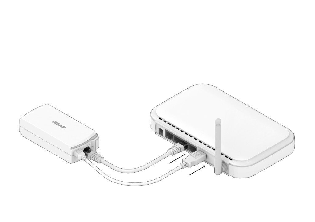
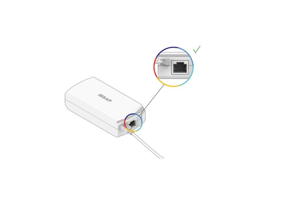
- Connect the Connection Unit to the router and to the power supply.
The Connection Unit can be powered via the router itself.
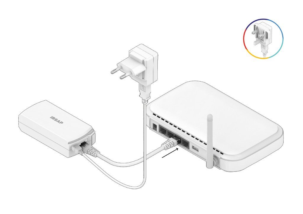
Alternatively, you can power the device via the mains, using the power supply with the EU adapter or the UK adapter.
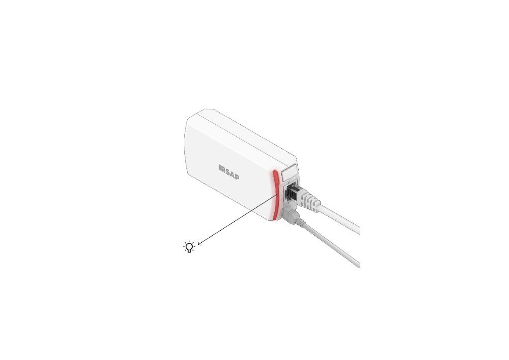
- Check the connection has been made: the LED signal will be red and flashing.
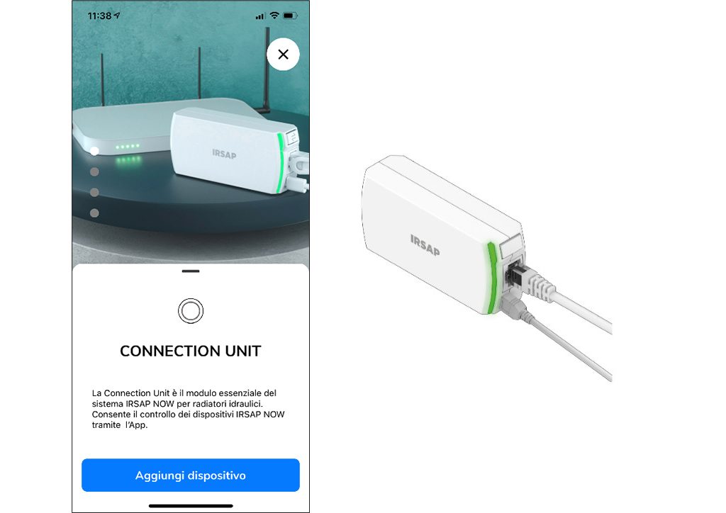
- Start the app and add the Connection Unit to the home configuration: follow the instructions and frame the QR code you find in the package, in this way the Connection Unit will be registered and associated with your home system. The led signal will be steady and green.
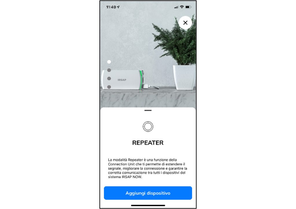
How to install and configure the Connection Unit in Repeater mode
- Connect the Repeater to the electrical socket (Warning: do not connect the Ethernet port!)
- Activate Repeater mode: Press the side button 5 times within 3 seconds. The led will flash red.
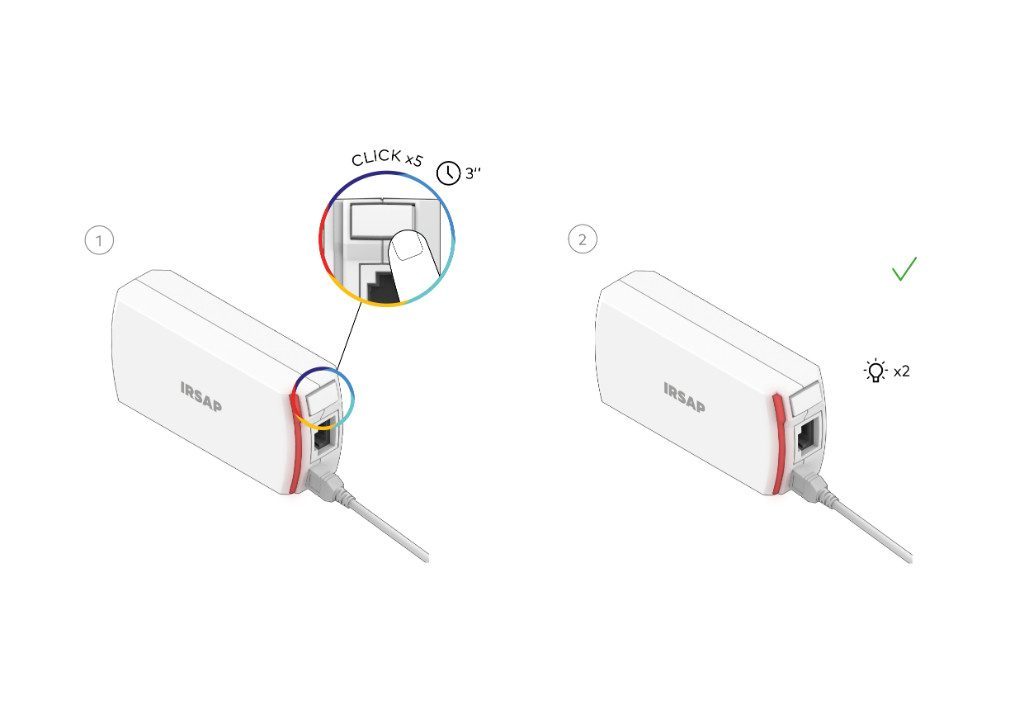
- Start the app and add the Connection Unit to the home configuration: follow the instructions and frame the QR code you find in the package, in this way the Connection Unit will be registered and associated with your home system. The led signal will be steady and green.
How to install and configure the Smart Valves
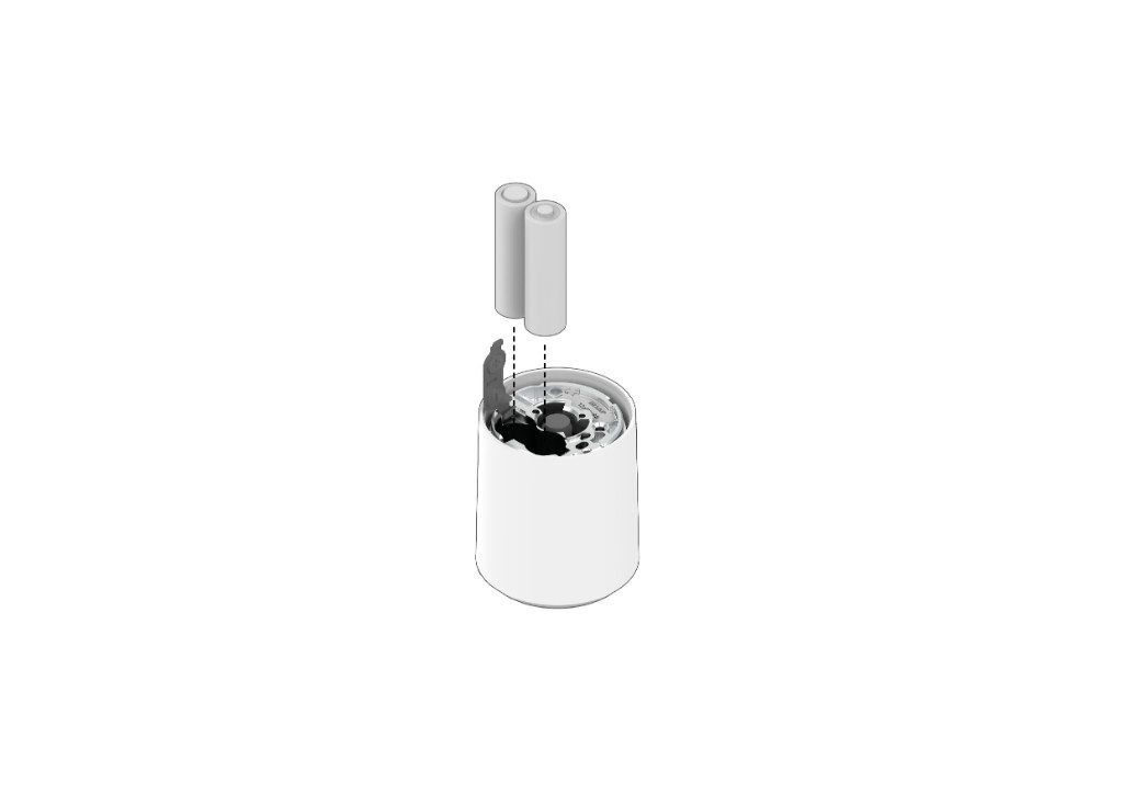
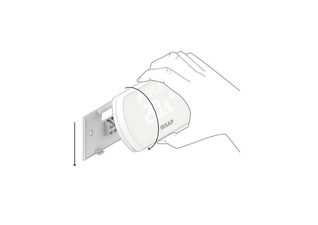
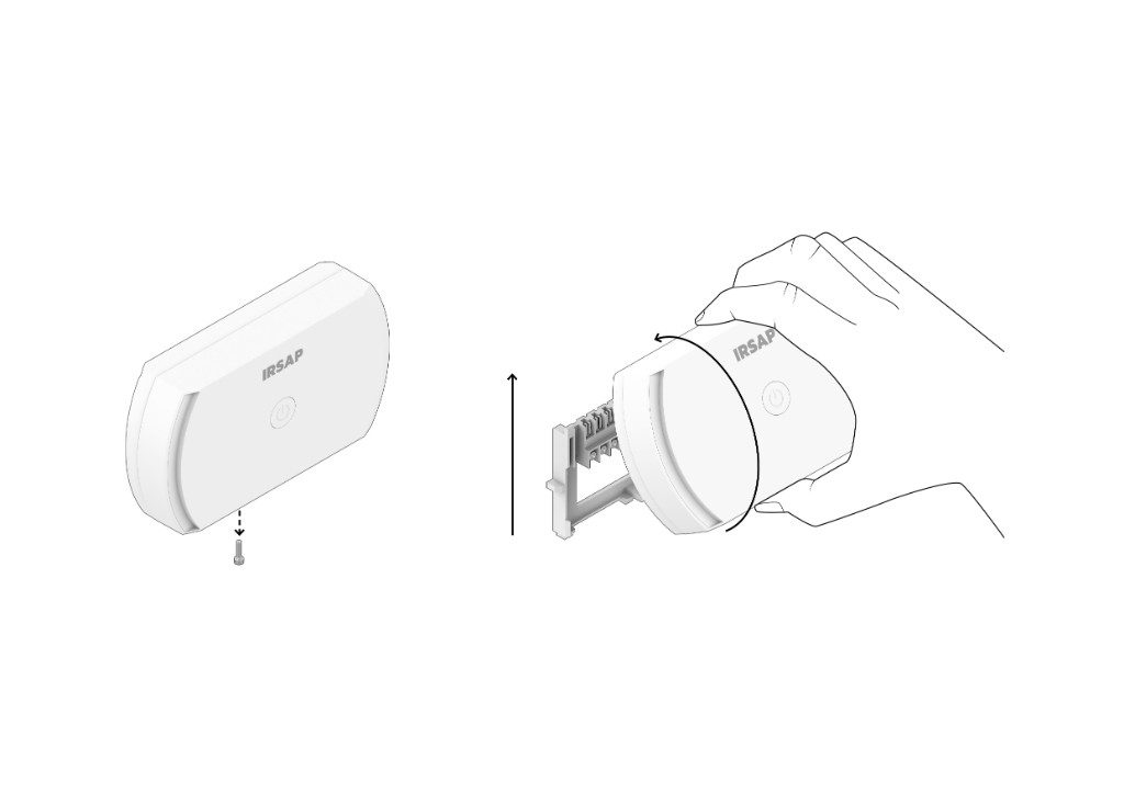
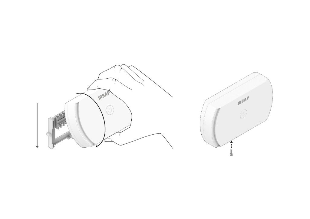
- Disassemble the back of the Smart Valve by holding it tight and turning the device clockwise. With one hand, hold the front part tightly and with the other, anchor the rear plastic fitted with a threaded ring nut.
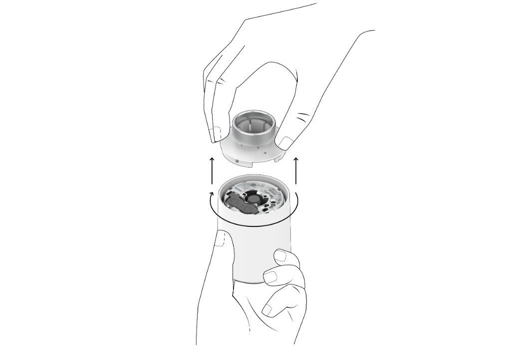
- Open the metal tab on the back of the device by sliding it and insert the batteries that are inside the package, then close the tab.
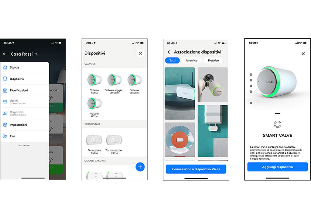
 3. Select "Menu -> Devices -> Add device -> Smart Valve" in the app and follow the steps for pairing the device
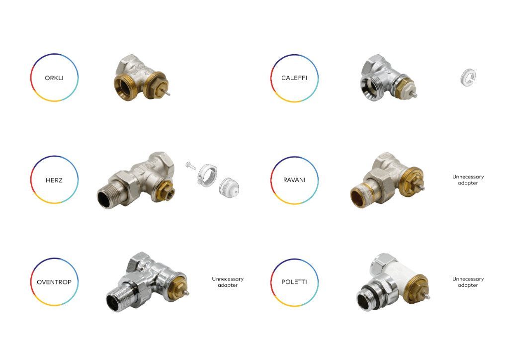
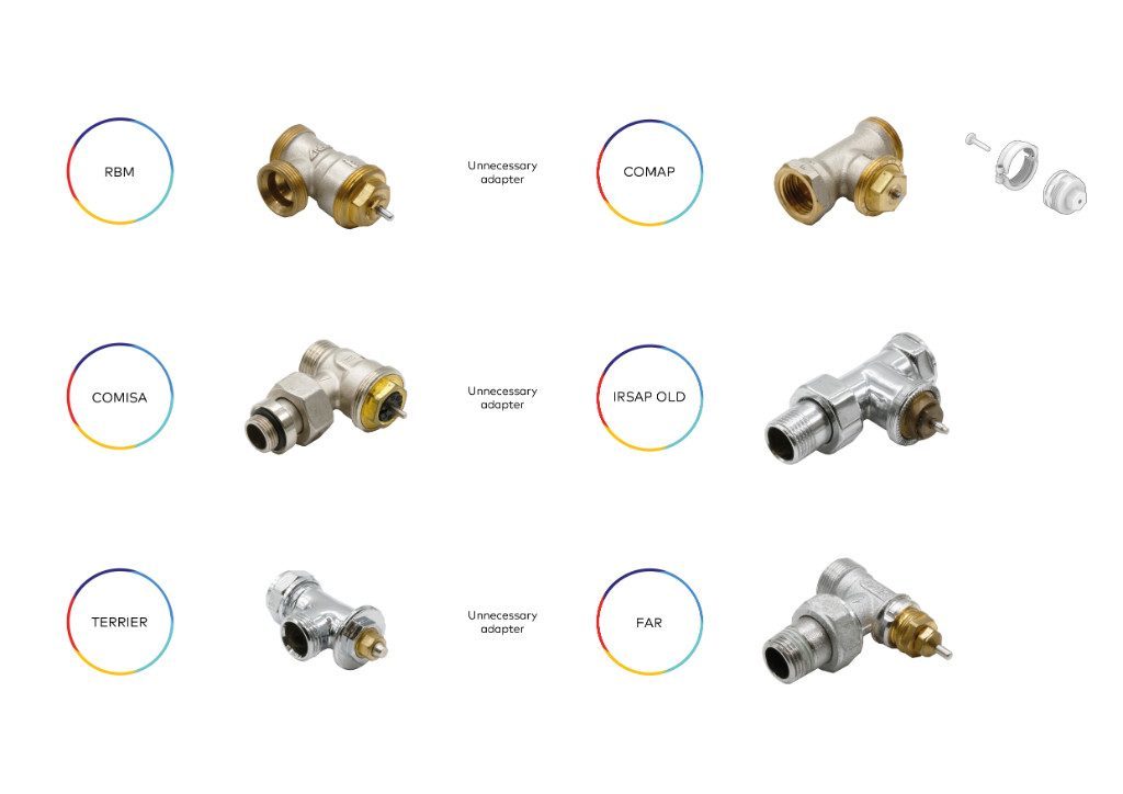
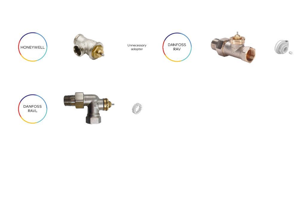
4. Remove the thermostatic head or valve cap from the radiator and check the type of hydraulic valve to use the appropriate adapter / pin, referring to the template inside the package. You will find below a selection of the most common valves with thermostatic option, and information on the use of which adapter to mount. 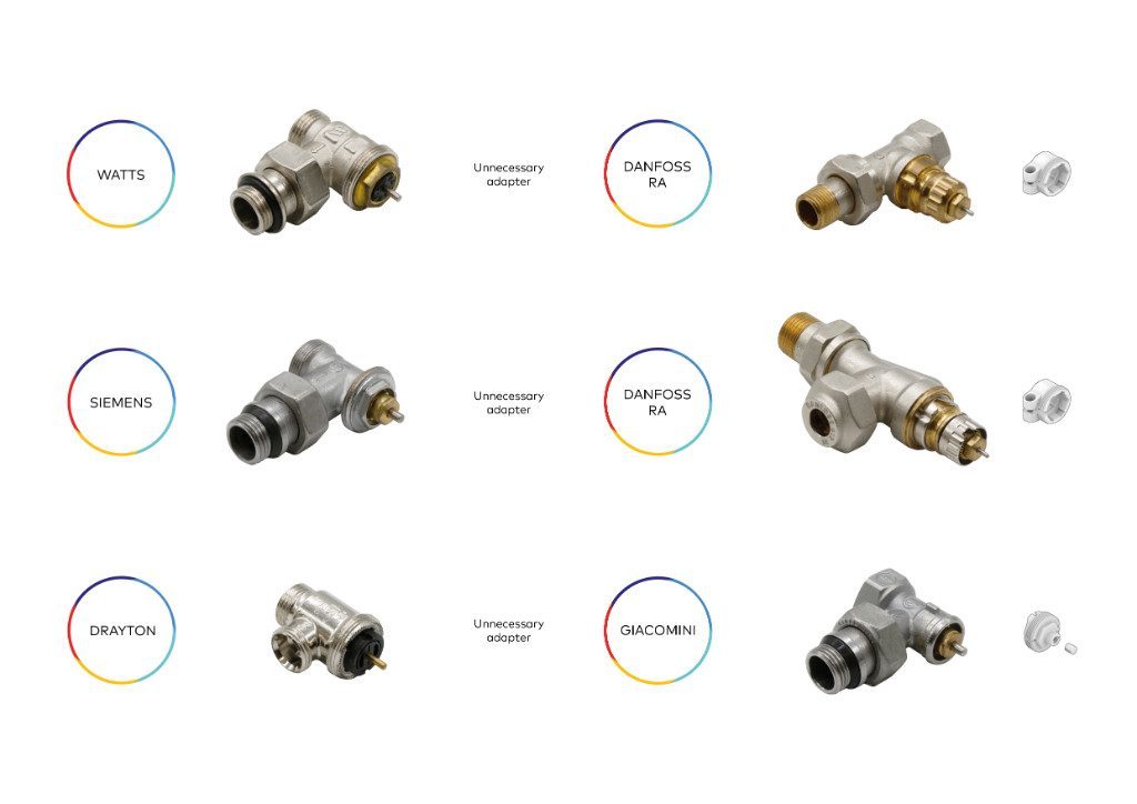
5. Install the Smart Valve rear attachment system to the hydraulic valve of the
radiator and tighten the locking ring.
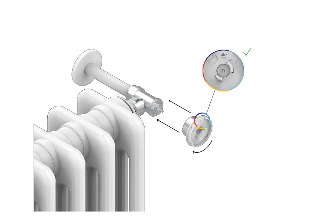
- Install the main body of the Smart Valve on the fastening system by holding it tight and
turning the device counter-clockwise.
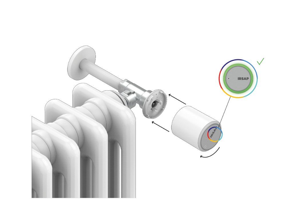 If the fixing is successful, the valve will give a green light signal. If not, we suggest that you disassemble the valve body, check the correctness of any adapter, tighten the closing ring and reinstall the valve. If the problem persists, contact IRSAP support.
How to install and configure the Smart Thermostat
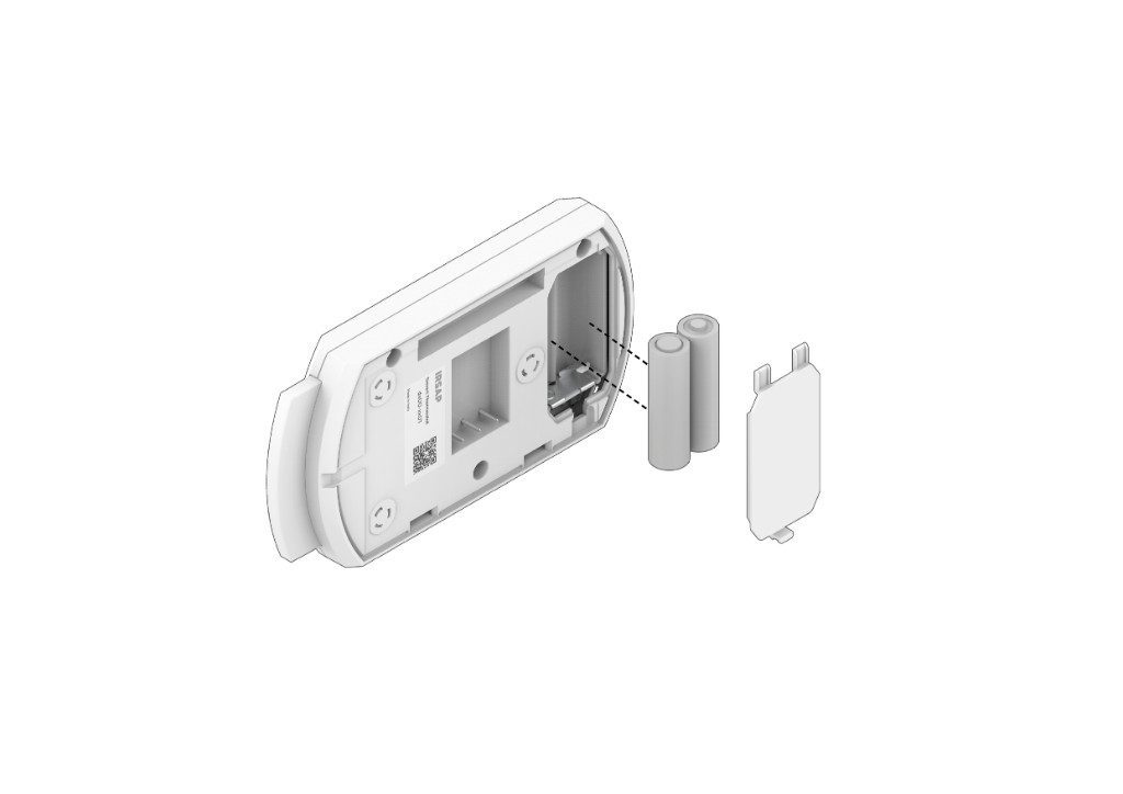
1. Remove the rear plastic cover.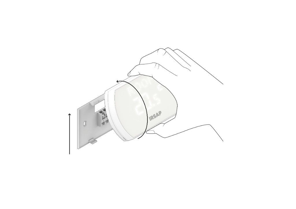
- Insert the batteries into the battery compartment.
- Select "Menu -> Devices -> Add device -> Smart Thermostat" in the app and follow the steps for pairing the device.
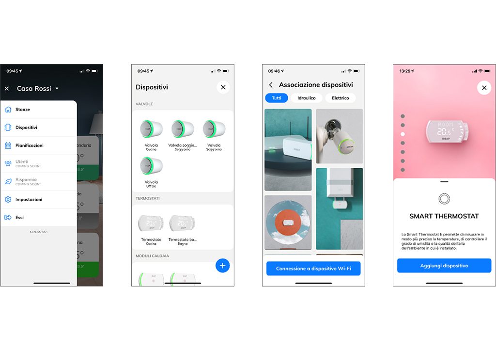
Table installation:
- Snap the Smart Thermostat back onto the back cover.
Place the Smart Thermostat on a shelf.
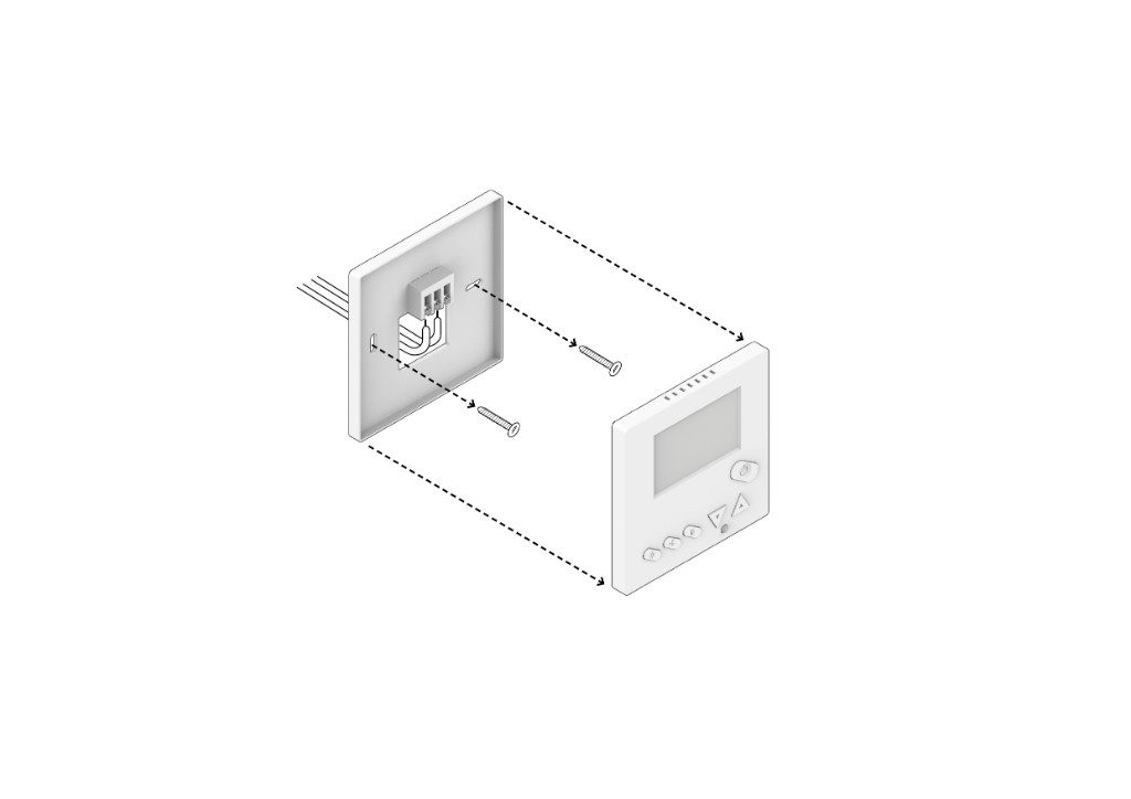
Wall installation:
- Remove power from the generator (Recommended: remove power from the whole house).
- Check the power failure (in case of lack of appropriate instrumentation, disconnect the general generator).

- Disassemble the previous thermostat and remember to take a picture of the connections present and to mark the wires.
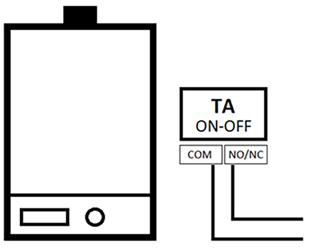
The Smart Thermostat mounts a relay to enable the management of a dry contact TA (without potential difference) of the generator.
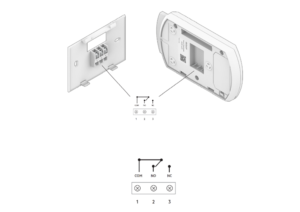
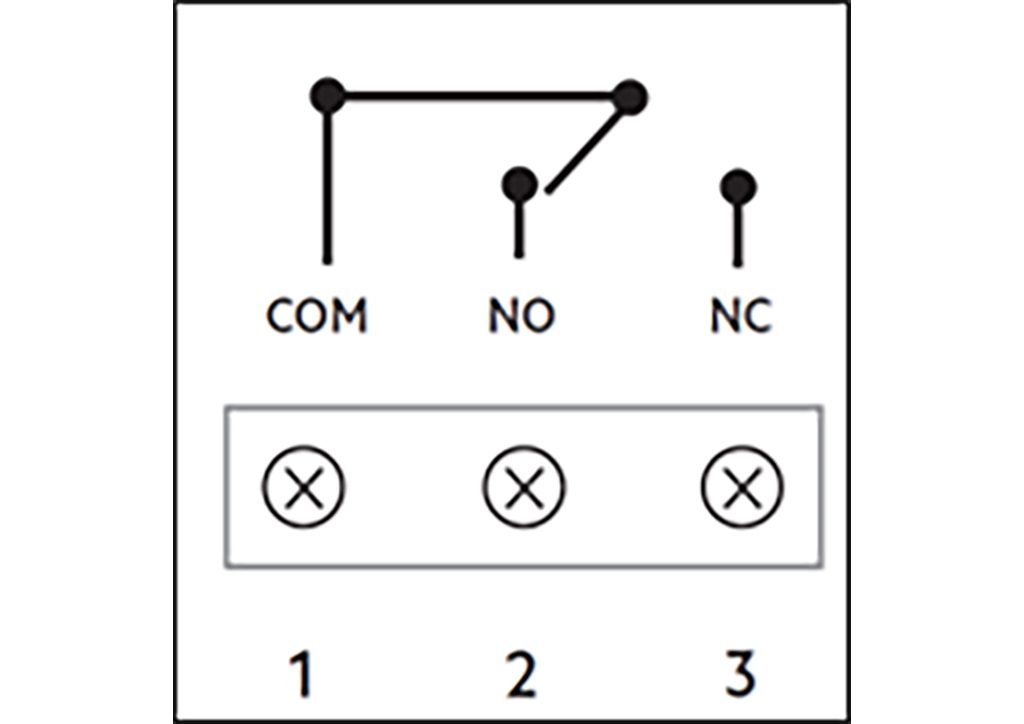
Identifies the 2 pole wires relating to the generator contact: they are marked as COM for the common and NO (or NO) for the normally open contact (or NC for the normally closed contact).
The Smart Thermostat works on batteries, so no cables should be connected to power the device. If there were cables to power the previous thermostat, insulate them.
Attach the back cover of the Smart Thermostat to the wall.
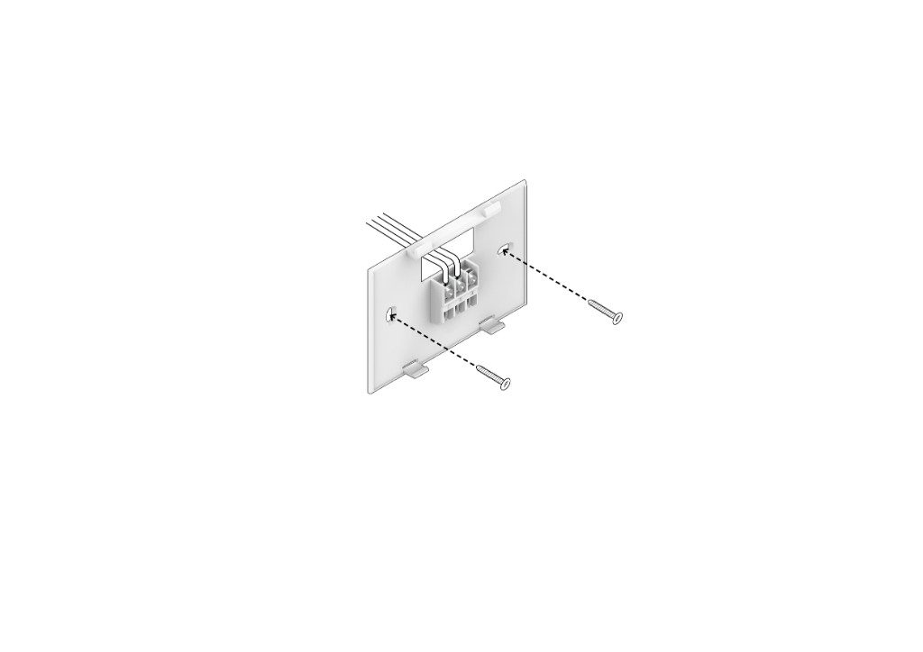
The cover has 2 holes for installation on the 3-module electrical box.
- Connect the 2 electrical wires according to the illustrations shown and the configuration on the generator.
Pass the wires through the upper slot of the cover: then insert the cables into the relative cable glands and secure them with the fixing screws.
The common electrical wire must be connected to the COM terminal, number 1 of the Smart Thermostat. Check the type of contact on the generator that provides for the connection of the room thermostat: if normally open, connect the second cable to the NO terminal (number 2) or if normally closed, connect it to the NC terminal (number 3).
- Attach the Smart Thermostat to the back cover.
Pay attention to the correct connection of the contacts with the metal forks.
- Restore power to the generator (or to the entire house, depending on the choice made previously).
How to install and configure the Starter
- Remove power from the generator (Recommended: remove power from the whole house).
- Check the power failure (in case of lack of appropriate instrumentation, disconnect the general generator).

- Remove any previous generator control (thermostat or control unit) and remember to take a picture of the connections present.
Mark the threads by inserting stickers to distinguish them.
Remove any wall plate from the previous Starter.

- Remove the back cover from our Starter.
First, unscrew the fixing screw located in the lower part of the device.
- Attach the back cover to the wall.
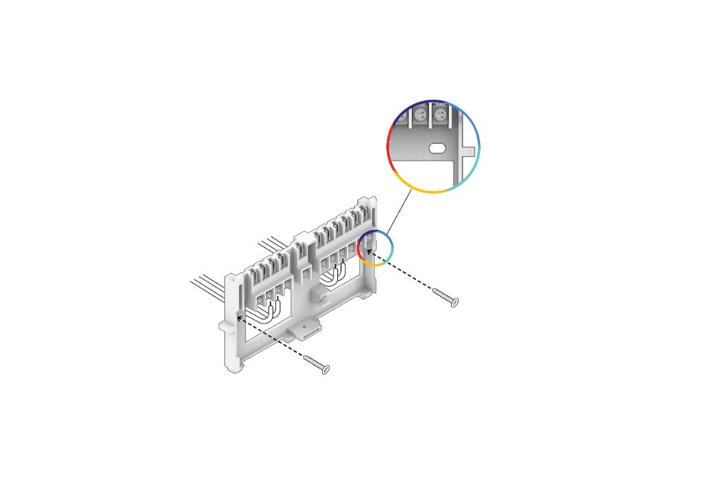
The cover has holes for installation on the 3 or 4 module electrical box.
- Connect the electrical wires according to the illustrations shown.
Pass the wires through the lower slots of the cover: then insert the cables into the relative cable glands and secure them with the fixing screws.
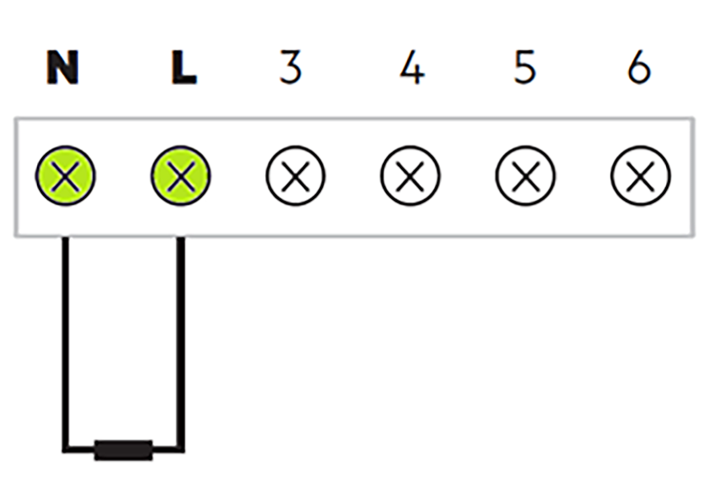
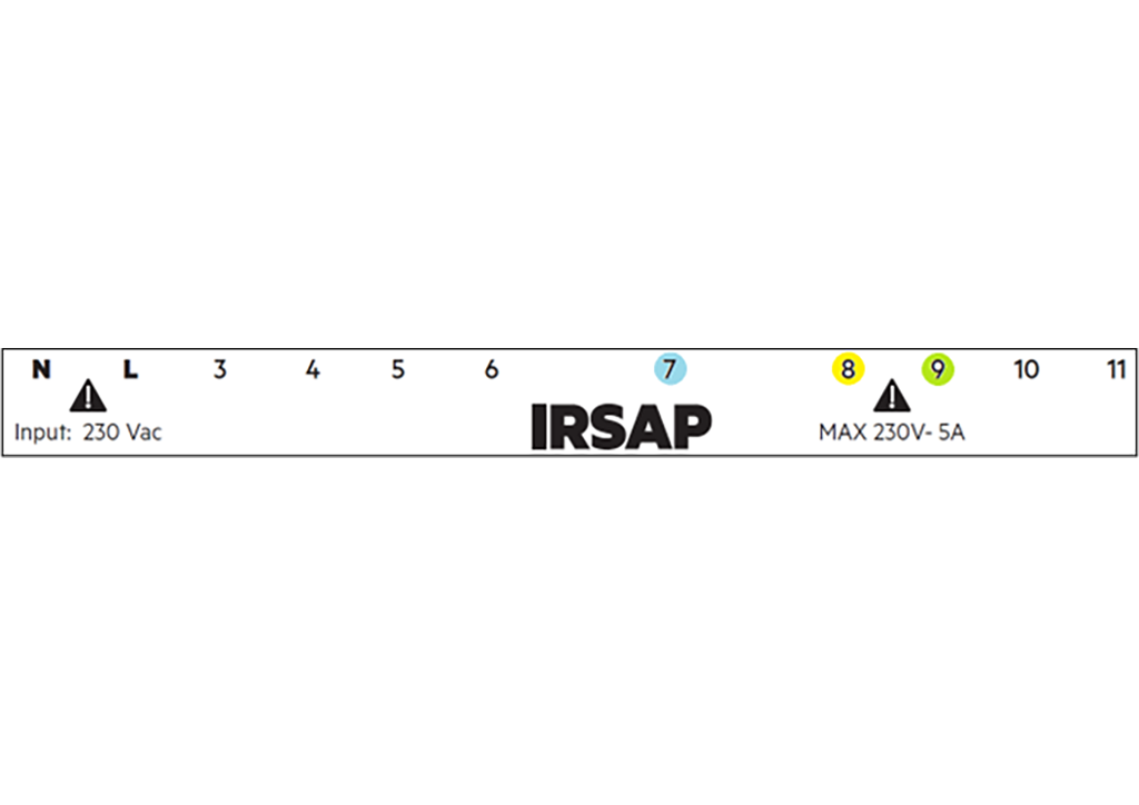
The power cables must be connected to terminals N and L: the neutral cable to terminal N (number 1) and the phase cable to terminal L (number 2).
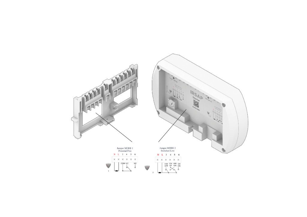
With the Starter it is possible to enable the management of 1 free CT contact (without potential difference) of the generator or 2 230 Vac outputs to activate hydraulic systems.
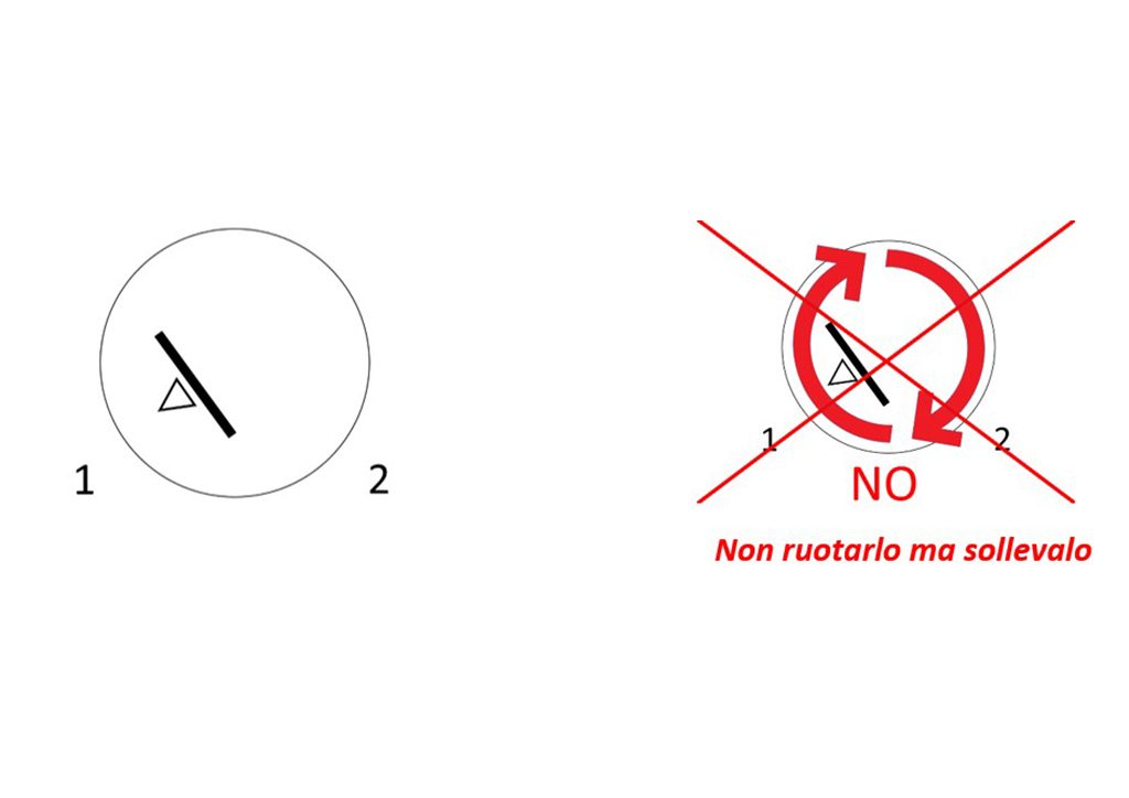
Using the jumper on the back of the Starter it is possible to choose between these 2 configurations: to change the position of the jumper, lift it (do not rotate it) using a screwdriver (or other suitable tools) and then insert it in the desired position 1 or 2, paying attention to the metal contacts.
Press until the jumper is fully inserted.
The Starter is also equipped with a 0-10V analog output for generators that support dynamic temperature management (for this function, an external power supply, 12-36V, must be provided).
Finally, the Starter has an OpenTherm communication interface, as a master.
The Opentherm and analog output (0-10V) functions are alternatives to each other.
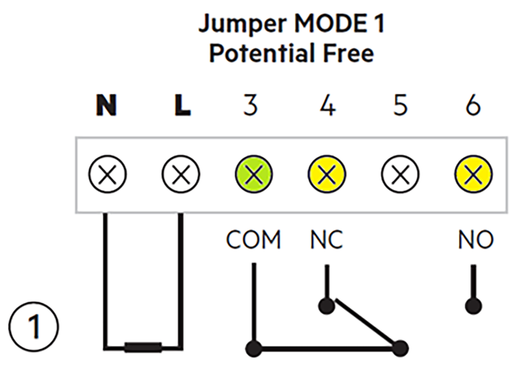
6a. To enable management of 1 CT free contact (without potential difference) of the generator, place the jumper in position 1.
Then connect the common electric cable to the COM terminal, number 3 of the Starter. Check the type of contact on the generator that provides for the connection of the room thermostat: if normally open, connect the second cable to the NO terminal (number 6) or if normally closed, connect it to the NC terminal (number 4).
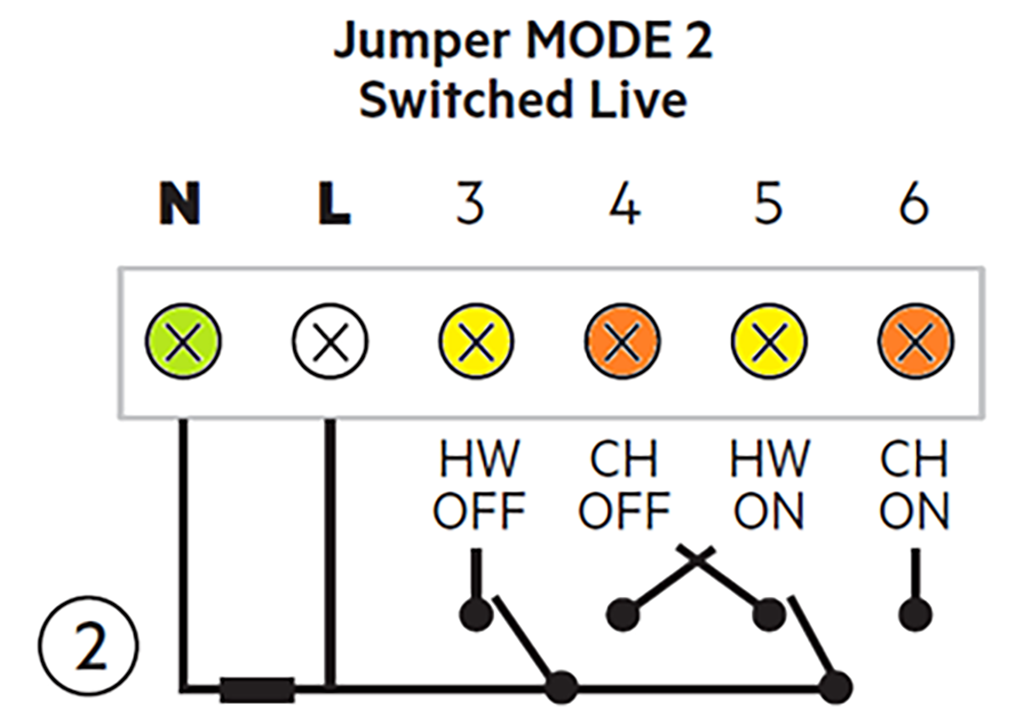
6b. To have 2 relays with 230 Vac output (maximum switch 10A with resistive load and maximum 5A with inductive load) to activate hydraulic systems (pumps, valves, coils, ...) place the jumper in position 2.
The 2 relays will thus provide 230 Vac each output: be careful to connect the cables correctly so as not to damage the connected equipment.
The first CH relay of the Starter manages the heating of the system.
Connect the common electrical wire to terminal N, number 1 of the Starter.
If a normally open contact is required for voltage control, connect the second cable to the CH ON terminal (number 6). If, on the other hand, a normally closed contact is required, connect the second cable to the CH OFF terminal (number 4).
The second HW relay of the Starter manages the system's domestic hot water.
Connect the common electrical wire to terminal N, number 1 of the Starter.
If a normally open contact is required for voltage control, connect the second cable to the HW ON terminal (number 5). If, on the other hand, a normally closed contact is required, connect the second cable to the HW OFF terminal (number 3).
6c. Some generators support temperature management for heating via a 0-10V analog input: based on the voltage supplied at the output of the starter, the generator regulates the water temperature.
The working curve used is the following:
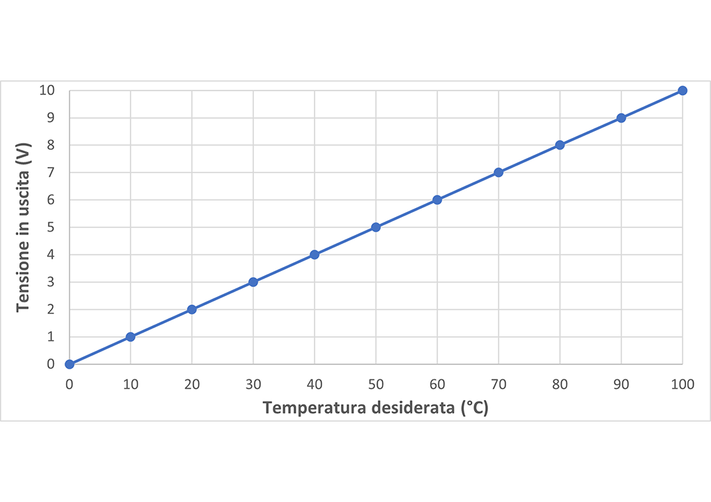
To use this function it is necessary to provide an external power supply to the Starter (in addition to the 230 Vac power supply): connect the ground to terminal 9 and the 12-36V power cable to terminal 8.
To have a 0-10V analog output from the Starter, connect the ground to terminal 9 and the other cable to terminal 7.
6d. As an alternative to 0-10V, the Starter also supports an OpenTherm communication interface, as a master.
Through this communication, the Starter and the generator exchange information such as the required temperature for heating and domestic hot water, requests for switching on or off, operating conditions of the generator, alarms or signals from the generator, ... The Starter takes on the role of master, then goes to replace any generator master control unit: pay attention that diagnostic information may be lost.

For OpenTherm communication with the Starter, connect cable A to terminal 8 and cable B to terminal 9.
- Apply the Starter to the back cover.
Pay attention to the correct connection of the contacts with the metal forks. Secure the device by screwing the screw into the hole at the bottom.
- Restore power to the generator (or to the entire home, depending on the choice made previously).).
- Select "Menu -> Devices -> Add device -> Starter" in the app and follow the steps for pairing the device.
Then go to the settings of the installed Starter and choose the desired mode (boiler relay, hot water relay, 0-10V interface or OpenTherm): configure the device based on the installation performed.
How to install and configure the IRSAP NOW System
Find out how to configure your home in the app:
CAUTION: The configuration screen appears at the end of the registration procedure (or at the end of the login procedure):
- Select 'Configure new home'
- Give your consent to proceed
- Enter the address where the system is installed (the house number is not compulsory)
- The fields will be filled in automatically
- Press the arrow at the bottom right to continue
- Enter the name you have chosen for your house and confirm it with the blue tick in the bottom right-hand corner.
How to configure installed products on the IRSAP NOW app
The IRSAP NOW system is designed to offer users high levels of comfort and energy efficiency in their homes.
In order for the system to work at maximum functionality, all NOW devices must be associated with the app and connected.
Pairing the devices is easy, you can find a step-by-step guide below:
Menu - Devices - '+' - choose device from image menu - add device following wizard instructions